Magnetic Particle Inspection of Crank Shafts
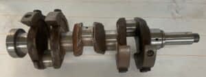
The crankshaft is a critical component in internal combustion engines and various mechanical systems. It plays a vital role in converting the reciprocating motion of pistons into rotational force, thereby propelling engine output. Comprising connected cylindrical sections known as crankpins and arms referred to as crank throws, the crankshaft transforms piston movement into rotational motion. This rotational energy is harnessed to power wheels, propellers, or other mechanical outputs. Given the substantial stresses endured, crankshafts demand precise manufacturing. The integrity of crankshafts is paramount, as any faults have the potential to trigger engine malfunctions and severe breakdowns. Therefore, ensuring the quality of crankshafts through rigorous production and inspections, such as magnetic particle inspection, becomes indispensable. This meticulous approach is crucial for guaranteeing the dependability and safety of machinery and engines.
Identifying issues preemptively through magnetic particle inspection allows for cost-effective preventive maintenance, minimizing downtime. Ultimately, this inspection method guarantees the integrity of crankshafts, prevents accidents, and aligns with stringent industry standards. It stands as a crucial practice for ensuring the longevity and optimal performance of engines.
The magnetization process for the crankshaft involves creating a circular magnetic field in two perpendicular directions to detect longitudinal flaws. This is achieved by passing a current through the length of the crankshaft.
The calculation of the headshot current is determined using the formula outlined in ASTM standards:
Head Shot Current = 20 X Diameter(mm)
In this formula, the diameter is considered twice the diameter of the lobe. For the detection of transverse flaws, a longitudinal magnetic field is required, generated by one or more encircling coils.
Following ASTM standards, the length of the crankshaft magnetized by the coil is equivalent to the inside diameter of the coil. To cover the entire crankshaft length, the coil needs to be moved to various points along the crankshaft, with each move separated by 90% of the coil diameter. This ensures the 10% overlap stipulated in the ASTM standards.
Formula for the Calculation of Coil Current:

In the above formula for the current requirement for coil shot, when calculating the L/D ratio, L must be equal to the inside diameter of the coil, not the overall length of the crankshaft. The diameter in the formula should be taken as the diameter of the journal.
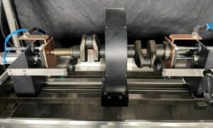
A bench-type machine is employed for magnetic particle testing on crankshafts. The crankshaft is positioned on stable rollers fitted on the machine’s head and tailstock. Pneumatic clamping, operated by an arrangement, secures the crankshaft from both ends. This ensures there is no sparking when a high current is passed through the crankshaft. The use of braided copper pads is recommended to eliminate arcing sparks.
Conventional Technique
A two-vector PLC-based bench-type magnetic crack detector machine is used to perform testing on the crank shafts
- Clean up & dry the crankshaft’s surface before inspecting.
- The crankshaft is placed on the steady rollers.
- Apply a magnetic solution bath to the crankshaft.
- Press the ‘Cycle Start’ button.
- The crankshaft automatically gets clamped.
- Stop the flow of the bath.
- Now, the current passes through the crankshaft.
- It shows up on the digital metering unit.
- The crankshaft automatically gets de-clamped.
- Inspect the crankshaft under UV light for longitudinal defects. Rotate on steady rollers.
- Move the coil to its 1st position
- Again apply the bath to the job.
- Press the ‘Cycle Start’ button.
- Stop the flow of the bath.
- Now, the current passes through the coil.
- It shows up on the digital metering unit.
- Inspect the crankshaft under UV light for transverse defects. Rotate on rollers.
- Move the coil to the next position & repeat the above 6 steps.
- Demagnetize
Multidirectional Technique
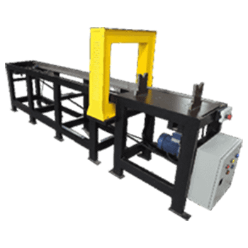
This custom-built machine employs two coils that are manipulated by pneumatic actuators. The automatic positioning of the coils streamlines the process of loading parts onto the machine. Spanning a length of 450mm from either end of the crankshaft, each coil contributes to a total coverage area of 900mm. Consequently, crankshafts with lengths of up to 900mm can be inspected using this apparatus.

- Ensure the crankshaft surface is cleaned and dried before inspection.
- Position the crankshaft on the stable rollers.
- Apply a bath to the crankshaft.
- Initiate the testing procedure by pressing the ‘Cycle Start’ button.
- The crankshaft will automatically be clamped, and the coils will move into position.
- Cease the bath flow.
- Electric current will pass through the crankshaft and the coils in multidirectional mode, displaying results on the digital metering unit.
- The crankshaft will automatically be released from the clamped position.
- Examine the crankshaft for defects under UV light in all directions while rotating it on the rollers.
- Conclude the process by demagnetizing the crankshaft.
Standard MPI Machines
Engineered for precision and efficiency, the Standard Bench Type Magnetic Particle Testing Machine is suitable for entry level testing.

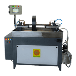
PLC Controlled MPI Bench
With PLC Controlled bench type Magnetic Particle Inspection Machine, you can accurately control the process parameters for reilable results.

Multidirectional MPI Bench
The ultimate solution for robust non-destructive testing, this machine offers multi-directional magnetization for inspection in all directions in one shot..
Demagnetizers
Demagnetizers stand as a key tool in maintaining excellence in production, with the flexibility to handle different materials and magnetism levels, coupled with energy-efficient and user-friendly design.