Magnetic Particle Inspection of Fasteners
Fasteners play a pivotal role across diverse industries, serving as integral components that secure structures and machinery. The dependable performance of fasteners is crucial for ensuring the safety, integrity, and efficiency of various applications. An essential aspect of upholding fastener quality involves the application of magnetic particle inspection (MPI).
MPI is a non-destructive testing method specifically employed to identify surface and near-surface defects in ferromagnetic materials. This testing technique holds paramount importance in both fastener manufacturing and maintenance processes. By subjecting fasteners to magnetic fields and introducing magnetic particles, potential flaws such as cracks, fissures, or discontinuities become visible. Early detection of these defects is vital in preventing catastrophic failures, ensuring that fasteners can effectively withstand the mechanical stresses they are subjected to.
In industries like aerospace, automotive, and construction, where fasteners bear substantial loads, MPI emerges as an indispensable tool. It plays a critical role in guaranteeing the structural integrity and reliability of fasteners, aligning with the overarching goal of enhancing overall product safety and longevity.
It’s worth noting that fasteners typically consist of two parts: the nut and the bolt. The testing methods for each component differ and are elaborated upon in the following sections.
MPI of Bolts
To effectively inspect a bolt, it is imperative to magnetize it in two directions that are perpendicular to each other. The detection of longitudinal flaws in the part is facilitated by employing a circular magnetic field.
The circular magnetic field is generated by passing a current through the entire length of the bolt. The calculation of the head shot current is carried out in accordance with the formula stipulated in ASTM standards:
Head Shot Current = 20 X Diameter(mm)
It is crucial to note that, in this formula, the diameter should be considered as the diameter of the threaded portion of the bolt.
For the detection of transverse flaws, a longitudinal magnetic field is required, and this is accomplished by utilizing an encircling coil.
Formula for calculation of coil current
In the above formula, the diameter should be taken as the diameter of the threaded portion of the bolt.
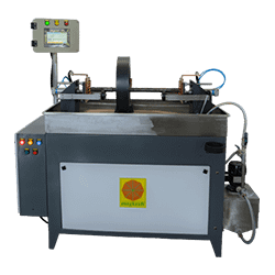
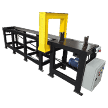
For bolt having length >=80mm: A horizontal bench-type machine is employed for magnetic particle testing of bolts. The testing process involves placing the bolt on stable rollers that are fitted on both the head and tailstock of the machine. To secure the bolt, a pneumatically operated arrangement is utilized for clamping from both ends. The use of pneumatic clamping is crucial to prevent sparking when a high current is passed through the bolt during the testing phase. As an additional safety measure, it is recommended to incorporate braided copper pads, which effectively eliminate the occurrence of arcing sparks, enhancing the overall safety and efficiency of the magnetic particle testing process for bolts.
For smaller bolts: In the magnetic particle testing process, a vertical bench-type machine is employed. The bolt is positioned vertically using a fixture, which is then placed inside a coil. A pneumatically operated mechanism is utilized to securely clamp the bolt from the top, ensuring stable positioning during the testing procedure. This setup allows for effective inspection of the bolt’s integrity using magnetic particle testing in a vertical orientation within the designated coil.
MPI of Nuts
In the testing process for nuts, a horizontal bench-type machine is employed. Multiple nuts, typically ranging from 5 to 10, are loaded onto a copper rod with a diameter approximately 20% smaller than the inside diameter of the nut. This copper rod is positioned between the headstock and tailstock of the machine, and a current is passed through the copper rod.
The calculation of the head shot current is performed in accordance with the formula outlined in ASTM standards. This calculation is crucial for ensuring the accurate and effective magnetic particle testing of the nuts.
Head Shot Current = 20 X Diameter(mm)
In the specified formula, it’s important to note that the diameter should be considered as the outer diameter of the nut. This parameter is essential for accurate calculations in the magnetic particle testing process.
The current applied as per this formula generates a circular magnetic field within the nuts. This magnetic field is effective for inspecting longitudinal defects in the nuts.
However, to detect transverse defects, a longitudinal magnetic field is required. This is achieved by employing an encircling coil, specifically designed for creating the necessary longitudinal field during the testing process.
Formula for calculation of coil current
In the above formula, for the purpose of simplicity of calculations, the following assumptions can be made.
L= Length of each nut X Number of Nuts
D= Outer diameter of Nut-Inner Diameter of Nut
Conventional Technique
- Clean up & dry the nut/bolt’s surface before inspecting.
- Place the bolt or the central conductor on the machine.
- Apply a magnetic solution bath to the nut/bolt.
- Initiate the testing sequence by pressing the ‘Cycle Start’ button.
- The bolt/central conductor automatically undergoes clamping.
- Stop the flow of the bath.
- Now, the current passes through the bolt or the central conductor.
- The current’s presence is registered on the digital metering unit.
- The part is automatically de-clamped.
- Inspect the nut/bolt under UV light for longitudinal defects. Rotate on steady rollers.
- Reapply the bath to the job.
- Initiate the testing sequence by pressing the ‘Cycle Start’ button.
- Stop the flow of the bath.
- Now, the current passes through the coil.
- The current’s presence is registered on the digital metering unit.
- Inspect the nut/bolt under UV light for transverse defects. Rotate on rollers.
- Demagnetize.
Multidirectional Technique
- Clean up & dry the nut/bolt’s surface before inspection.
- Place the bolt or central conductor on the steady rollers.
- Apply a bath to the nut/bolt.
- Initiate the testing sequence by pressing the ‘Cycle Start’ button.
- The bolt or central conductor will automatically undergo clamping.
- Stop the flow of the bath.
- Now, the current will pass through the bolt or central conductor & the coil in multidirectional mode.
- It will show up on the digital metering unit.
- The part will automatically get de-clamped.
- Inspect the nut/bolt under UV light for defects in all directions. Rotate on rollers.
- Demagnetize.


