Magnetic Particle Inspection of Axle Shafts
Axles serve as a foundational component for the operational efficiency of automobiles by transmitting power from the engine to the wheels while bearing the weight of the vehicle. They play a crucial role in facilitating smooth steering, supporting suspension movement, and enabling wheel rotation. Both front and rear axles contribute significantly to the stability, control, and overall performance of a vehicle, thereby ensuring safe and efficient transportation.
The application of Magnetic Particle Inspection (MPI) is essential in enhancing the safety and reliability of axle shafts. This inspection method involves magnetizing the shafts and introducing magnetic particles, making surface and near-surface defects visible. MPI, being a non-destructive technique, is pivotal for the early detection of cracks and flaws, thereby preventing potential catastrophic failures. Adhering to industry standards, MPI enables proactive maintenance, early identification of defects, and compliance with quality control measures. Its cost-effectiveness and non-destructive nature make MPI indispensable for ensuring the structural integrity of axle shafts across various industries.
For the proper inspection of the axle shaft, magnetization in two perpendicular directions is necessary. To identify longitudinal flaws in the part, a circular magnetic field is employed.
The circular magnetic field is generated by passing a current through the length of the axle. The head shot current is calculated according to the formula outlined in ASTM standards:
Head Shot Current = 20 X Diameter of shaft (in mm)
It’s crucial to note that in the above formula, the diameter should be taken as the diameter of the shaft, excluding the flange.
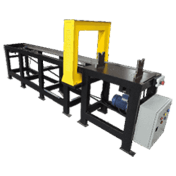
For the detection of transverse defects, a longitudinal magnetic field is required, and this is achieved by employing one or more encircling coils. According to ASTM standards, the length of the axle shaft magnetized by the coil should be equal to the inside diameter of the coil.
To cover the entire length of the axle, the coil must be repositioned to different points along the length, with each relocation separated by 90% of the coil diameter. This practice ensures compliance with the 10% overlap specified in the ASTM standards, guaranteeing a thorough inspection of the axle shaft for both longitudinal and transverse defects.
Formula for calculation of coil current
Additionally, it’s crucial to note in the aforementioned formula for determining the current requirement in a coil shot that when calculating the L/D ratio, L should be equivalent to the inside diameter of the coil, not the overall length of the axle.
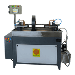
The magnetic particle testing process for axles is carried out using a bench-type machine. The axle is positioned on stable rollers attached to both the head and tailstock of the machine. To secure the axle firmly, a pneumatic clamping system is employed from both ends. This pneumatic clamping mechanism is designed to prevent sparking when a high current is applied to the axle during testing. As an added precautionary measure, it is recommended to utilize braided copper pads, effectively eliminating the occurrence of arcing sparks and ensuring a safer testing environment.
Conventional Technique
A two vector PLC based bench type magnetic crack detector machine is used to perform testing on the axles.
- Clean up & dry the axle’s surface before inspecting.
- Place the axle on the steady rollers.
- Apply a magnetic solution bath to the axle.
- Press the ‘Cycle Start’ button.
- The axle automatically clamps.
- Stop the flow of the bath.
- Now, the current passes through the axle.
- It registers on the digital metering unit.
- The axle automatically de-clamps.
- Inspect the axle under UV light for longitudinal defects. Rotate on steady rollers.
- Position the coil to its 1st position.
- Apply the bath to the job again.
- Press the ‘Cycle Start’ button.
- Stop the flow of the bath.
- Now, the current passes through the coil.
- It shows up on the digital metering unit.
- Inspect the axle under UV light for transverse defects. Rotate on rollers.
- Move the coil to the next position & repeat the above 6 steps.
Multidirectional Technique
In this custom-made machine, two coils are employed, and their positioning is automated through pneumatic actuators. The automatic movement of coils streamlines the loading of the part onto the machine. Each coil effectively covers a length of 450mm from each end of the axle. Consequently, with two coils in use, an area of 900mm is covered. This configuration allows the machine to accommodate and inspect axles with a length of up to 900mm.
Testing Procedure for Conventional Machines
- Ensure the axle’s surface is thoroughly cleaned and dry before inspection.
- Position the axle onto the steady rollers.
- Apply a bath to the axle surface.
- Initiate the testing sequence by pressing the ‘Cycle Start’ button.
- The axle will automatically undergo clamping, and the coils will move into position.
- Halt the bath flow.
- The current will then pass through the axle and the coils in a multidirectional mode.
- Observe the results on the digital metering unit.
- The axle will automatically be de-clamped.
- Inspect the axle under UV light for defects in all directions. Rotate it on the rollers for comprehensive examination.
- Conclude the process by demagnetizing the axle.


