Magnetic Particle Inspection of Ring Gears
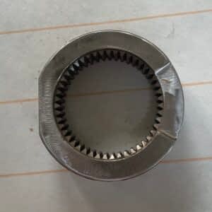
Ring gears play a pivotal role in various mechanical systems, encompassing automotive transmissions, industrial machinery, and wind turbines. These circular components, adorned with teeth on their outer edges, are instrumental in transmitting torque and facilitating rotational motion. In automotive applications, ring gears are indispensable for the smooth starting of engines and gear changes.
Given their critical function in power transmission, the integrity of ring gears is paramount. Magnetic Particle Testing (MPT) stands out as a crucial inspection technique employed to ensure their reliability. MPT, a non-destructive testing method, is applied to detect surface and near-surface defects in ferromagnetic materials. By applying magnetic particles and exposing the ring gears to a magnetic field, potential cracks, fractures, or discontinuities become visible, enabling timely identification and preventive maintenance.
In safety-critical sectors such as automotive and industrial machinery, the use of MPT for ring gears is essential to prevent catastrophic failures that could lead to downtime, accidents, or costly repairs. Regular MPT inspections facilitate the early detection of flaws, enhancing operational efficiency and overall system reliability.

Like all other components, ring gears also necessitate a magnetic field in two perpendicular directions for comprehensive defect inspection. A circular magnetic field is created by passing a central conductor made from copper through the ring and passing current through this conductor. If the ring’s diameter is small, the conductor can be centered within the ring, and current can be applied using the formula:
Head Shot Current = 20 X Diameter (mm)
In this formula, the diameter should be considered as the outer diameter of the ring.
For larger rings, an offset conductor method can be employed to test the part with lower amperage. In this method, the conductor is positioned on one side of the inner periphery of the ring gear. The periphery covered by the conductor is equal to four times its diameter.
After one shot, the ring is rotated to check the next portion. This process is repeated until the entire ring is inspected.
The diameter of the conductor can be adjusted so that the entire ring can be examined in 3-4 shots.
Head Shot Current = 20 X Diameter (mm)
In this formula, the diameter should be taken as the outer diameter of the copper rod.
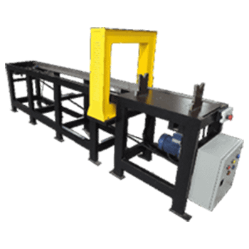
For longitudinal magnetization, an encircling coil is utilized. The current requirement for the coil must be determined using QQI shims, as standard formulas are not applicable to the geometry of the ring gear.
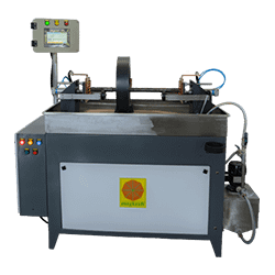
A horizontal bench-type machine is utilized for magnetic particle testing on ring gears. The ring gear is positioned on the steady rollers placed on the machine. A copper conductor connected to a pneumatic cylinder is employed for central conductor magnetization.
The arrangement is illustrated in the picture below.

- Ensure the Ring gear’s surface is clean and dry before inspection.
- Position the Ring gear on the steady rollers.
- Apply the magnetic solution bath to the Ring gear.
- Initiate the ‘Cycle Start’ process.
- Observe as the central conductor extends, passes through the gear, and connects to the tail stock.
- Halt the bath flow.
- Allow the current to pass through the central conductor.
- View the results on the digital metering unit.
- Examine the Ring gear for longitudinal defects under UV light. Rotate on steady rollers as needed.
- If utilizing the offset conductor method, rotate the gear and repeat the steps until the entire ring is covered.
- Press the ‘Cycle Start’ button.
- Reapply the bath to the job.
- Stop the bath flow.
- Allow the current to pass through the coil.
- View the results on the digital metering unit.
- Inspect the Ring gear for transverse defects under UV light. Rotate on rollers.
- Complete the demagnetization process.


